Description
Features
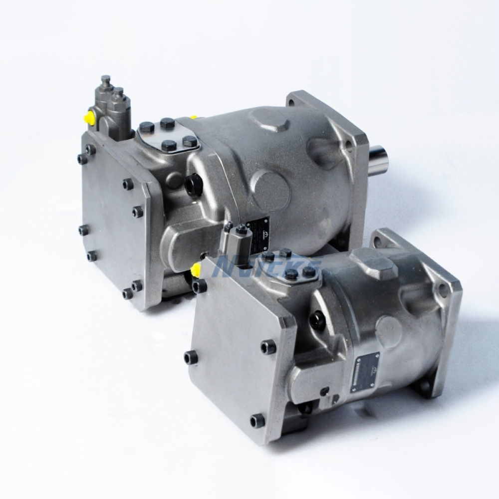
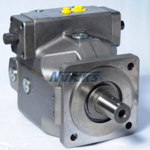
Variable displacement pump with axial piston rotary group of swash-plate design for hydro-static drives in open circuit.
Flow is proportional to the drive speed and displacement.
The flow can be infinitely varied by adjusting the swash-plate angle.
Hydro-statically unloaded cradle bearing
Port for measurement sensor on the high-pressure port
Low noise level
Low pressure pulsation
High efficiency
High resistance to cavitation,suction pressure drops and housing pressure peaks
Universal through drive
Order model/standard product
|
01
|
02
|
03
|
04
|
|
05
|
06
|
|
07
|
08
|
09
|
10
|
11
|
12
|
13
|
|
LA10VS
|
O
|
|
|
/
|
32
|
|
–
|
V
|
|
B
|
|
|
|
|
Axial piston unit
|
01
|
Swash-plate design, variable, nominal pressure 280 bar, maximum pressure350 bar |
LA10VS
|
Operating mode
Size (NG)
|
03
|
Geometric displacement |
045
|
071
|
100
|
140
|
Control device 045 071 100 140
|
04
|
Two-point control, directly operated
|
·
|
·
|
·
|
·
|
DG
|
|
Pressure controller hydraulic
|
·
|
·
|
·
|
·
|
DR
|
|
With flow control
|
hydraulic
|
X-T open
|
·
|
·
|
·
|
·
|
DRF
|
|
X-T plugged
|
·
|
·
|
·
|
·
|
DRS
|
|
Pressure cut-off
|
hydraulic
|
Remotely operated
|
·
|
·
|
·
|
·
|
DRG
|
|
Electric
|
Negative control
|
U=12V
|
·
|
·
|
·
|
·
|
ED71
|
|
U=24V
|
·
|
·
|
·
|
·
|
ED72
|
|
Electric
|
Positive control
|
U=12V
|
·
|
·
|
·
|
·
|
|
|
U=24V
|
·
|
·
|
·
|
·
|
|
|
Power control with pressure cut-off
|
hydraulic
|
Control begin
|
To 50 bar
|
·
|
·
|
·
|
·
|
LA5D
|
|
From 51 to 90 bar
|
·
|
·
|
·
|
·
|
LA6D
|
|
From 91 to 160 bar
|
·
|
·
|
·
|
·
|
LA7D
|
|
From 160 to 240 bar
|
·
|
·
|
·
|
·
|
LA8D
|
|
Above 240 bar
|
·
|
·
|
·
|
·
|
LA9D
|
|
Remotely operated
|
hydraulic
|
Control begin
|
See LA.D
|
·
|
·
|
·
|
·
|
LA.DG
|
|
Flow control, X-T plugged
|
hydraulic
|
Control begin
|
See LA.D
|
·
|
·
|
·
|
·
|
LA.DS
|
|
Electrically overridable (negative control)
|
See LA.D
|
·
|
·
|
·
|
·
|
LA.S
|
Series
Direction of rotation
|
06
|
Viewed on drive shaft
|
clockwise |
R
|
| Counter-clockwise |
L
|
Seal
|
07
|
FKM (fluor-caoutchouc) |
V
|
Drive shafts
|
08
|
Parallel keyed shaft ISO 3019-1(SAE J744)limited suitability for through drive
|
·
|
·
|
·
|
·
|
·
|
P
|
|
Splined shaft
|
Standard shaft
|
·
|
·
|
·
|
·
|
·
|
S
|
|
ANSI B92.1a
|
Similar to shaft “S” however for higher input torque
|
·
|
·
|
–
|
–
|
–
|
R
|
Mounting flange
The following must be taken into account during project planning: Excessive current levels (I>1200 mA at 12V orl>600mA at 24 V) to the ER solenoid can result in undesired pressure increases which can lead to pump or system damage.
Therefore:
-Use lmax current limiter solenoids.
-A sandwich plate pressure reducing valve can be used to protect the pump in the event of overflow.
Service line ports 045 071 100 140
|
10
|
SAE flange ports at top, at bot tom, on opposite side, UNF fastening thread with universal through drive |
Without pulsation damping
|
·
|
·
|
·
|
·
|
22U
|
|
With pulsation damping, not for high-speed
|
·
|
·
|
·
|
·
|
32U
|
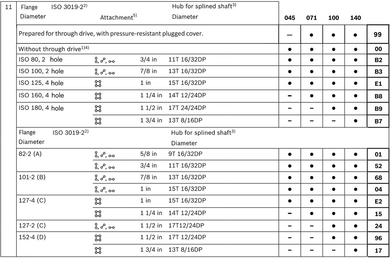
Through drives (for fitting options)
Rotary group version
|
12
|
12 Standard rotary group(noise-optimized for n=1500/1800 rpm) |
·
|
·
|
·
|
·
|
E
|
| High-speed(with port plate version 72U only) |
·
|
·
|
·
|
·
|
S
|
Connector for solenoids
|
13
|
Without connector(without solenoid, with hydraulic control only, without code) |
|
| HIRSCHMANN connector-without suppressor diode |
H
|

Installation instructions
General,
The axial piston unit must be filled with hydraulic fluid and air bled during commissioning and operation. This must also be considered with a long-term standstill.
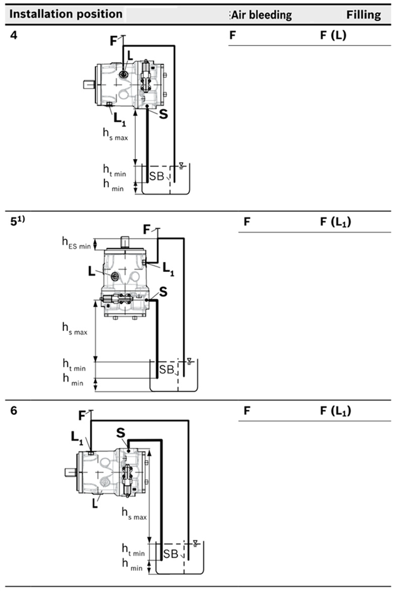
Particularly with the “drive shaft up/down” installation position, filling and air bleeding must be carried out completely as there is, for example, a danger of dry running. The case drain fluid in the pump housing must be discharged to the reservoir via the highest available drain port (L,L₁). For combinations of multiple units, the case drain fluid must be drained off at each pump. We recommend laying separate drain lines. If this is not possible, a shared drain line may need to be laid. If a shared drain line is used for this purpose, make sure that the case pressure in each pump is not exceeded. In the event of pressure differences at the drain ports of the units,the shared drain line must be changed so that the minimum permissible case pressure of all connected units is not exceeded in any situation. If this is not possible, separate drain lines must be laid if necessary.
To achieve favorable noise values, decouple all connecting lines using elastic elements and avoid above-reservoir installation.
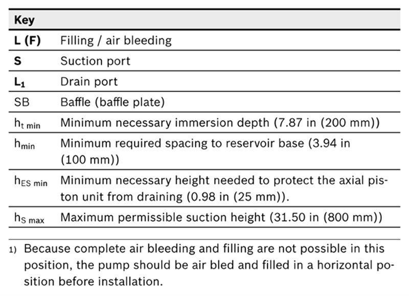
In all operating conditions, the suction line and drain line must flow into the reservoir below the minimum fluid level.The permissible suction height hs results from the overall loss of pressure. However, it must not be higher than hs max=31.50 in (800 mm). The minimum suction pressure at port S (see the technical data on page 64) must not be fallen short of during operation and at cold starting either. When designing the reservoir, ensure that there is sufficient distance between the suction line and the drain line. This prevents the heated, return flow from being drawn directly back into the suction line.
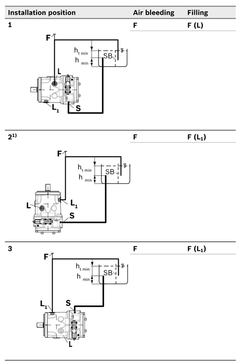
Installation position
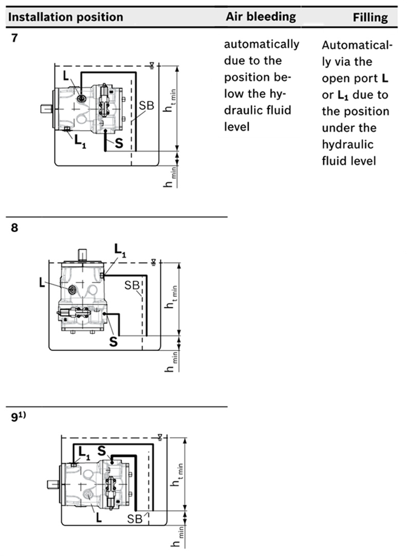
See the following examples 1 to 9. Further installation positions are available upon request. Recommended installation position: 1 and 3
Below-reservoir installation (standard)
Below-reservoir installation is when the axial piston unit is installed outside of the reservoir below the minimum fluid level.
Note
Port F is part of the external piping and must be provided by the customer to make filling and air bleeding easier.
Above-reservoir installation
Above-reservoir installation means the axial piston unit is installed above the minimum fluid level of the reservoir. To prevent the axial piston unit from draining in position 5, the height difference hES min must be at least 0.98 in (25 mm). Observe the maximum permissible suction height hs max=31.50 in (800 mm).
A check valve in the case drain line is only permissible in individual cases. Consult us for approval.
1)Because complete air bleeding and filling are not possible in this position, the pump should be air bled and filled in a horizontal position before installation.
Inside-reservoir installation
Reservoir installation is when the axial piston unit is installed in the reservoir below the minimum fluid level. The axial piston unit is completely below the hydraulic fluid.
If the minimum fluid level is equal to or below the upper edge of the pump, see chapter “Above-reservoir installation”.
Axial piston units with electrical components (e.g., electric control, sensors) may not be installed in a reservoir below the fluid level.
Assembly note
Due to the compact design of the casing, socket-head screws with a hexagon socket must be used to attach the axial piston pump. Please observe the maximum permissible surface pressure according to VDI2230.
Apart from this, you should take into account the information regarding tightening torques in the operating instruction.
Project planning notes
▶ The LA10VSO axial piston variable pump is intended to be used in open circuit.
▶ Project planning, installation and commissioning of the axial piston units requires the involvement of skilled personnel.
▶ Before using the axial piston unit, please read the corresponding instruction manual completely and thoroughly. If necessary, this can be requested from us.
▶ Before finalizing your design, request a binding installation drawing.
▶ The specified data and notes contained herein must be observed.
▶ Depending on the operating conditions of the axial piston unit (working pressure, fluid temperature), the characteristic curve may shift. The characteristic curve may also shift due to the dither frequency or control electronics.
▶ Preservation: Our axial piston units are supplied as standard with preservation protection for a maximum of 12 months. The preservation periods apply under optimal storage conditions, details of which can be found in the data sheet 90312 or the instruction manual.
▶ Not all versions of the product are approved for use in a safety function according to ISO 13849. Please consult the proper contact us if you require reliability parameters (e.g.MTTFd) for functional safety.
▶ Depending on the type of control used, electromagnetic effects can be produced when using solenoids. Applying a direct voltage signal (DC) to solenoids does not create electromagnetic interference (EMI) nor is the solenoid affected by EMI. Electromagnetic interference (EMI) potential exists when operating and controlling a solenoid with a modulated direct voltage signal (e.g. PWM signal) Appropriate testing and measures should be taken by the machine manufacturer to ensure other components or operators (e.g. with pacemaker) are not affected by this potential.
▶ Pressure controllers are not safeguards against pressure overload. Be sure to add a pressure relief valve to the hydraulic system.
▶ For drives that are operated for a long period of time with constant rotational speed, the natural frequency of the hydraulic system can be stimulated by the excitation frequency of the pump (rotational speed frequency×9). This can be prevented with suitably designed hydraulic lines.
▶ Please note the details regarding the tightening torques of port threads and other threaded joints in the instruction manual.
▶ The ports and fastening threads are designed for the Pmax permissible pressures of the respective ports, see the connection tables. The machine or system manufacturer must ensure that the connecting elements and lines correspond to the specified application conditions (pressure, flow, hydraulic fluid, temperature) with the necessary safety factors.
▶ The working ports and function ports are only intended to accommodate hydraulic lines.

Reviews
There are no reviews yet.