
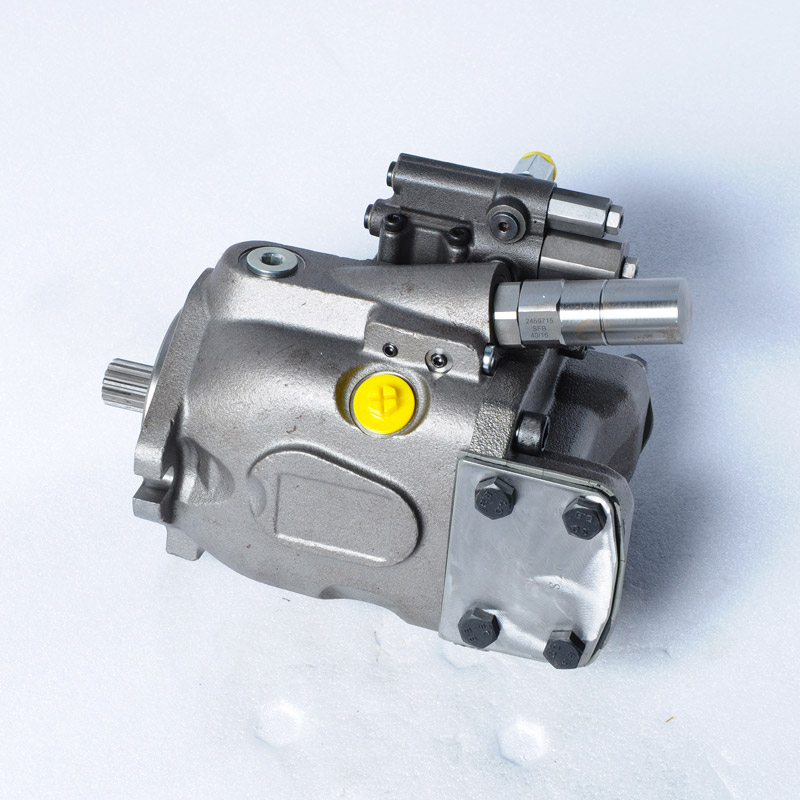
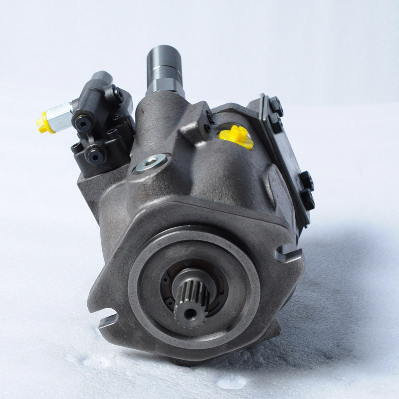
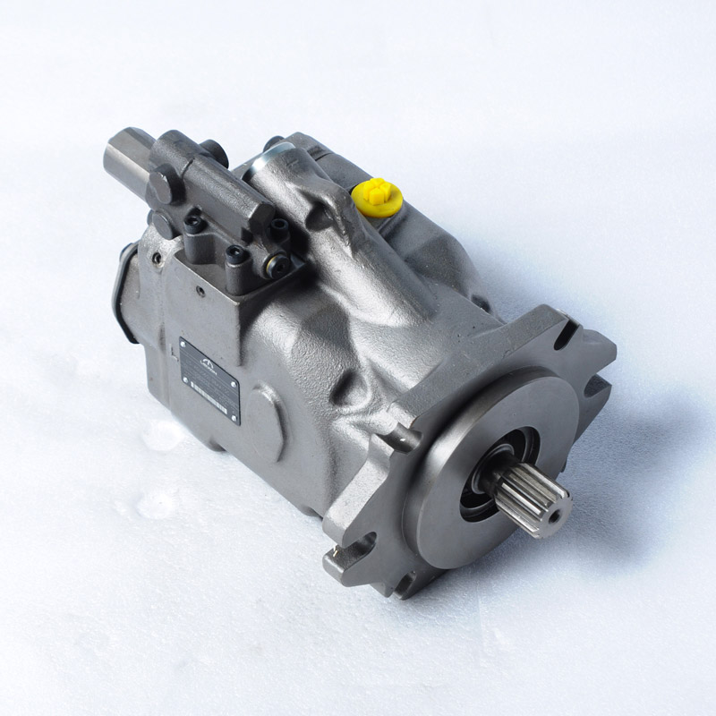
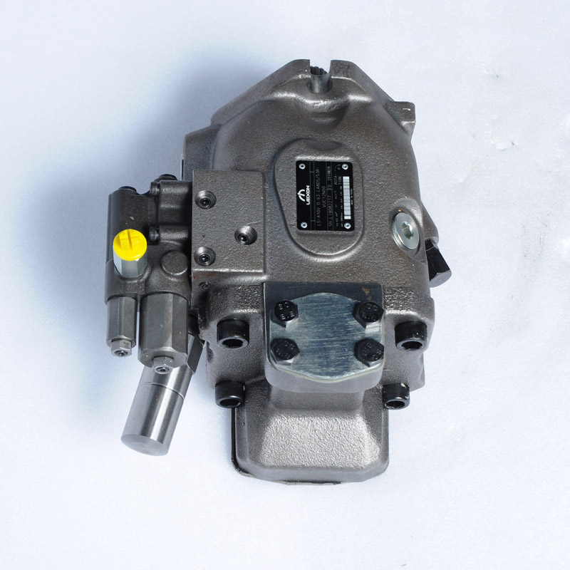
Description
Features
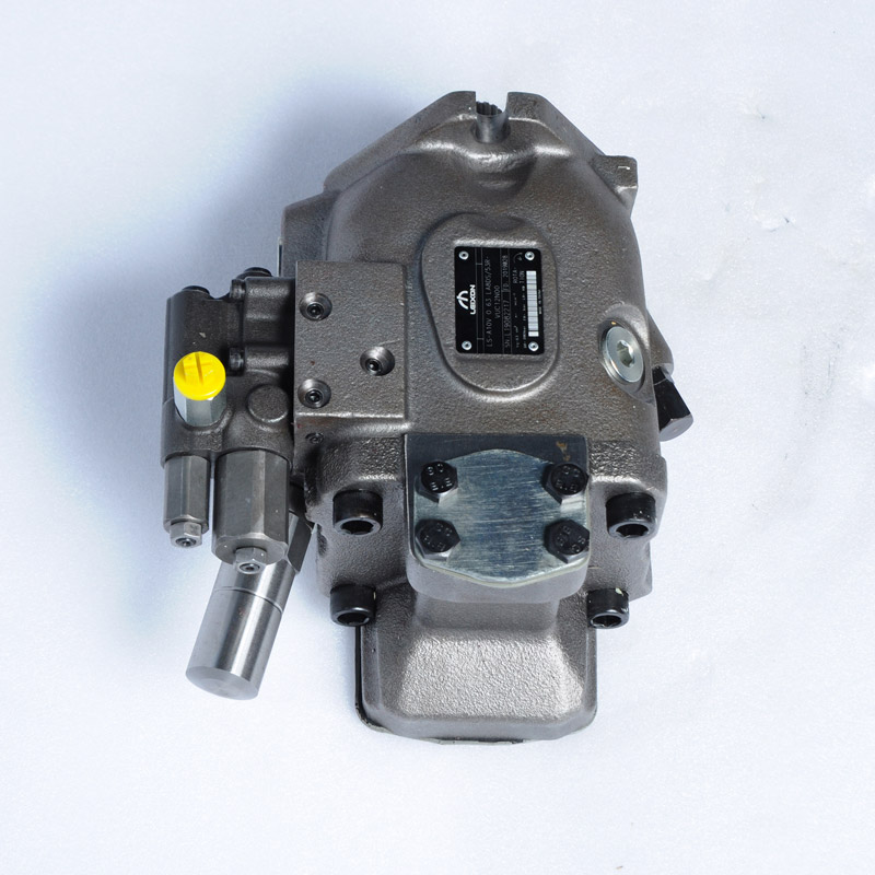
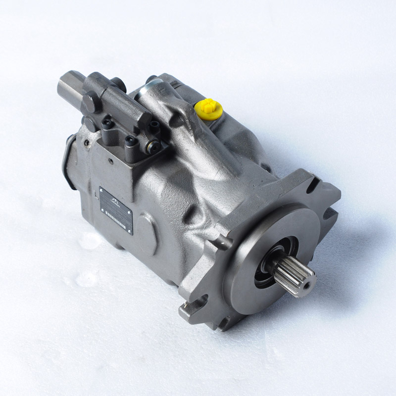
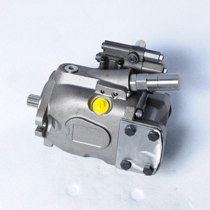
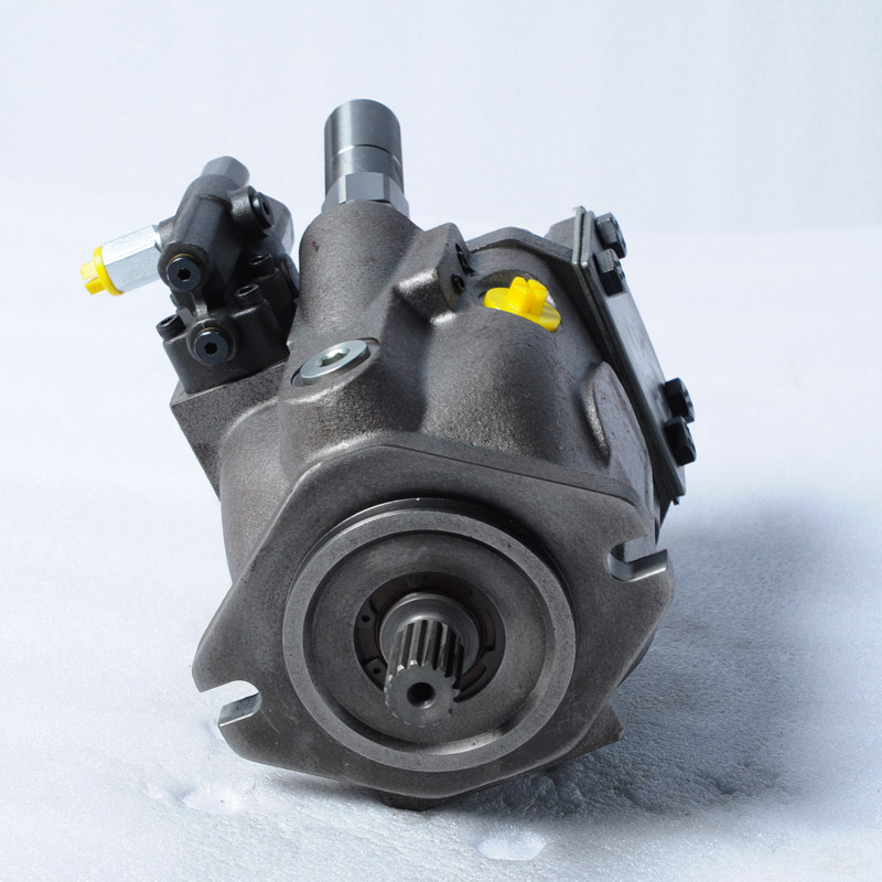
Order code series 52
|
01 |
02 |
03 |
04 |
|
05 |
06 |
|
07 |
08 |
09 |
10 |
11 |
12 |
|
LA10VS |
O |
|
|
/ |
52 |
|
– |
V |
|
|
|
|
|
Axial piston unit 10 28 45 60 85
|
01 |
Swash-plate design, variable, nominal pressure 250 bar, maximum pressure315 bar |
· |
– |
– |
– |
– |
LA10VS |
|
– |
· |
· |
· |
· |
LA10V |
Operating mode
|
02 |
Pump, open circuit |
O |
Size (NG)
|
03 |
Geometric displacement |
10 |
28 |
45 |
60 |
85 |
Control device 10 28 45 60 85
|
04 |
Pressure controller hydraulic |
· |
· |
· |
· |
· |
DR |
|||
|
With flow control |
· · |
X-T open |
· |
· |
· |
· |
· |
DFR |
||
|
X-T plugged |
With flushing function |
· |
· |
· |
· |
· |
DFR1 |
|||
|
Without flushing function |
– |
· |
· |
· |
· |
DRSC |
||||
|
Pressure cut-off |
hydraulic |
Remotely operated |
· |
· |
· |
· |
· |
DRG |
||
|
Electric |
Negative control |
U=12V |
– |
· |
· |
· |
· |
ED71 |
||
|
U=24V |
– |
· |
· |
· |
· |
ED72 |
||||
|
Electric |
Positive control |
U=12V |
– |
· |
· |
· |
· |
ER71 |
||
|
U=24V |
– |
· |
· |
· |
· |
ER72 |
||||
|
Differential pressure control |
Electric control (negative control) |
– |
。 |
。 |
。 |
· |
|
|||
Series 10 28 45 60 85
| 05 | Series 5, index 2 |
· |
· |
· |
· |
· |
52 |
Direction of rotation
|
06 |
Viewed on drive shaft |
clockwise |
R |
| Counter-clockwise |
L |
Seal
|
07 |
FKM (fluor-caoutchouc) |
V |
Drive shafts
|
08 |
Splined shaft ANSI B92.1a |
Standard shaft |
· |
· |
· |
· |
· |
S |
|
Similar to shaft “S” however for higher input torque |
– |
· |
· |
· |
· |
R |
||
|
Reduced diameter, limited suitability for through drive |
· |
· |
· |
· |
· |
U |
||
|
Similar to shaft “U”, however for higher torque |
– |
· |
· |
· |
· |
W |
||
|
Parallel keyed shaft DIN 6885 limited suitability for through drive |
· |
– |
– |
– |
– |
P |
||
Mounting flange
|
09 |
ISO 3019-2 (ISO) |
2-hole |
· |
– |
– |
– |
– |
A |
|
ISO 3019-1 (SAE) |
2-hole |
· |
· |
· |
· |
· |
C |
|
|
4-hole |
– |
– |
– |
· |
– |
D |
Working ports
|
10 |
SAE flange ports at top, fastening thread, metric |
rear |
Not for through drive |
– |
· |
· |
· |
· |
11 |
|
At side, opposite |
For through drive |
– |
· |
· |
· |
· |
12 |
||
|
At side, offset 90° |
Not for through drive; available only for counter-clockwise direction of rotation |
– |
– |
· |
– |
– |
13 |
||
| Threaded port, metric |
Rear |
Not for through drive |
· |
– |
– |
– |
– |
14 |
Through drives (for fitting options)
|
11 |
Without through drive |
· |
· |
· |
· |
· |
N00 |
Connector for solenoids
|
12 |
Without connector (without solenoid, with hydraulic control only, without code) |
· |
· |
· |
· |
· |
|
| DEUTSCH – molded connetor, 2-pin – without suppressor diode (for electric controls) |
– |
· |
· |
· |
· |
P |

Order code series 53
|
01 |
02 |
03 |
04 |
|
05 |
06 |
|
07 |
08 |
09 |
10 |
11 |
12 |
|
LA10VS |
O |
|
|
/ |
53 |
|
– |
V |
|
|
|
|
|
Axial piston unit 18 28 45 63 72 85 100
|
01 |
Swash-plate design, variable, nominal pressure 250 bar, maximum pressure315 bar |
· |
· |
· |
· |
· |
· |
· |
LA10V |
Operating mode
|
02 |
Pump, open circuit |
O |
Size (NG)
|
03 |
Geometric displacement |
18 |
28 |
45 |
63 |
72 |
85 |
100 |
Control device
|
04 |
Pressure controller |
hydraulic |
· |
· |
· |
· |
· |
· |
· |
DR |
|||
|
With flow control |
hydraulic |
X-T open |
· |
· |
· |
· |
· |
· |
· |
DFR |
|||
|
X-T plugged |
With flushing function |
· |
· |
· |
· |
· |
· |
· |
DFR1 |
||||
|
Without flushing function |
· |
· |
· |
· |
· |
· |
· |
DRSC |
|||||
|
Pressure cut-off |
hydraulic |
Remotely operated |
· |
· |
· |
· |
· |
· |
· |
DRG |
|||
|
Electric |
Negative control |
U=12V |
· |
· |
· |
· |
· |
· |
· |
ED71 |
|||
|
U=24V |
· |
· |
· |
· |
· |
· |
· |
ED72 |
|||||
|
Electric |
Positive control |
U=12V |
· |
· |
· |
· |
· |
· |
· |
ER71 |
|||
|
U=24V |
· |
· |
· |
· |
· |
· |
· |
ER72 |
|||||
|
Differential pressure control |
Electric control (negative control) |
。 |
。 |
。 |
。 |
。 |
· |
· |
|
||||
|
Power control with pressure cut-off |
hydraulic | Start of control from | 10~35 bar |
· |
· |
· |
· |
· |
· |
· |
LA5D |
||
| 36 ~70 bar |
· |
· |
· |
· |
· |
· |
· |
LA6D |
|||||
| 71~105 bar |
· |
· |
· |
· |
· |
· |
· |
LA7D |
|||||
| 106~140 bar |
· |
· |
· |
· |
· |
· |
· |
LA8D |
|||||
| 141~230 bar |
· |
· |
· |
· |
· |
· |
· |
LA9D |
|||||
|
Remotely operated |
hydraulic | Start of control |
· |
· |
· |
· |
· |
· |
· |
LA.DG |
|||
|
Flow control, X-T plugged |
hydraulic | Start of control |
· |
· |
· |
· |
· |
· |
· |
LA.DS |
|||
| Electrically overridable (negative control) |
· |
· |
· |
· |
· |
· |
· |
LA.S |
|||||
Series
| 05 | Series 5, index 3 |
· |
· |
· |
· |
· |
· |
· |
53 |
Direction of rotation
|
06 |
Viewed on drive shaft |
clockwise |
R |
| Counter-clockwise |
L |
Seal
|
07 |
FKM (fluor-caoutchouc) |
V |
Drive shafts
|
08 |
Splined shaft ANSI B92.1a |
Standard shaft |
· |
· |
· |
· |
· |
· |
· |
S |
|
Similar to shaft “S” however for higher input torque |
· |
· |
· |
· |
· |
· |
– |
R |
||
|
Reduced diameter, limited suitability for through drive |
· |
· |
· |
· |
· |
· |
· |
U |
||
|
Similar to shaft “U”, however for higher torque |
– |
· |
· |
· |
· |
· |
· |
W |
Mounting flange
|
09 |
ISO 3019-1 (SAE) |
2-hole |
· |
· |
· |
· |
· |
· |
· |
C |
|
4-hole |
– |
– |
– |
· |
· |
· |
· |
D |
Working ports
|
10 |
SAE flange ports fastening thread, metric |
rear |
Not for through drive |
· |
· |
· |
· |
· |
· |
· |
11 |
|
At side, opposite |
For through drive |
· |
· |
· |
· |
· |
· |
· |
12 |
||
|
At side, offset 90° |
Not for through drive; available only for counter-clockwise direction of rotation |
– |
– |
· |
– |
– |
– |
– |
13 |
Through drives (for fitting options)
|
11 |
Without through drive |
· |
· |
· |
· |
· |
· |
· |
N00 |
Connector for solenoids
|
12 |
Without connector (without solenoid, with hydraulic control only, without code) |
· |
· |
· |
· |
· |
· |
· |
|
| DEUTSCH – molded connetor, 2-pin – without suppressor diode (for electric controls) |
· |
· |
· |
· |
· |
· |
· |
P |
Reviews
There are no reviews yet.